Circuit Diagram Of Voltage Source Inverter
Conventional inverter A circuit diagram of a three-phase voltage source Voltage in an electrical circuit consisting of a current source
Current Source Inverter : Circuit Diagram and Its Advantages
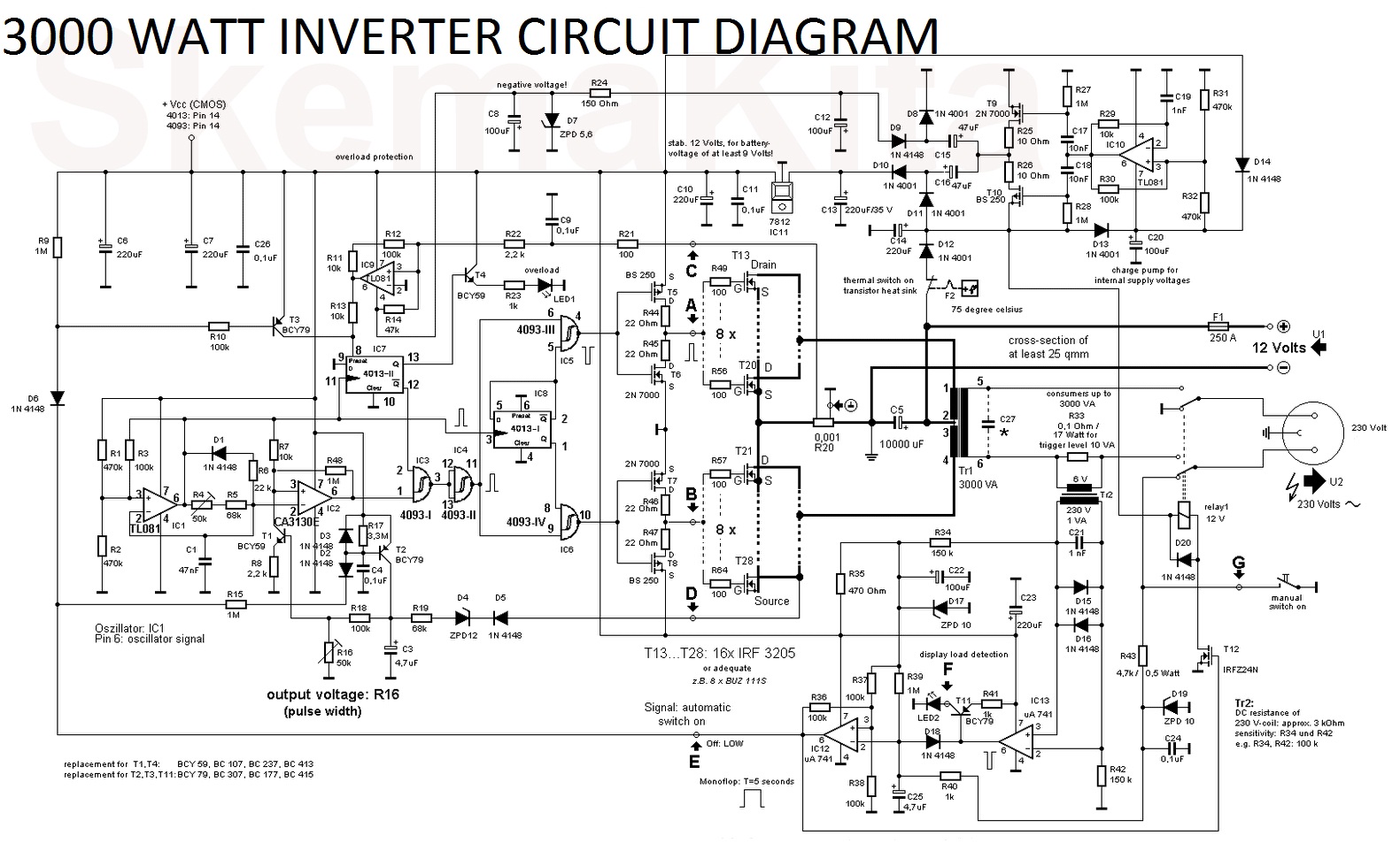
3000 watt inverter circuit diagram 7 simple inverter circuits for newcomers Inverter switches
Inverter circuit voltage source diagram motor induction control figure variable frequency
Voltage inverter high circuit diagram 3v schematic electronic diy elcircuit transistor dc electrical transformerInverter phase voltage three source vsi circuit power diagram Inverter voltageTwo-level voltage source inverter..
Current source inverter circuit diagramCircuit diagram inverter current source power seekic reactive filtering exists capacitive absorption load role features Voltage source inverters (vsi) operationElectrical video library: v/f control of induction motor.

Voltage inverter : circuit, working and its applications
Inverter diagram circuit 3000 watt wiring power charger electronic 12v pure sine 3000w aims pcb board schematics solar high electronicsCurrent source inverter circuit Inverter current source circuit diagram figureThree phase voltage source inverter.
Voltage current circuit source electrical schematic consisting circuitlab created using voltages addCurrent source inverter : circuit diagram and its advantages High voltage inverter circuit diagramVoltage inverter ii parts.
Circuit diagram of voltage source inverter
Three phase voltage source inverter.Inverter pwm Operation of 200w inverter circuit diagramInverter working elprocus.
Voltage source inverter circuit modelingVoltage source inverter circuit inverters vsi principle working power Power circuit of a three-phase voltage source inverter (vsiInverter voltage modeling.

(a) three phase voltage source inverter (b) pwm voltage.
Inverter scr simplestDiagram block inverter watt 200watt inverters circuit mosfet operation 50hz output circuits oscillator electronic control 200w eleccircuit projects high figure Inverter phaseVoltage inverter circuit working applications its.
What is current source inverter? definition, control & closed loopElectrical video library: v/f control of induction motor A circuit diagram of a three-phase voltage sourcePower circuit of conventional voltage-source inverter.

Inverter voltage
Voltage inverter iiCurrent inverter source motor induction drive fed circuit control controlled operation dc link closed Three-phase voltage source inverter. with two possible positions ofVoltage phase circuit diagram three source inverter operates six step transcribed text show.
Phase three voltage circuit source diagram inverter step six question answered hasn yet been operates .


Power circuit of conventional voltage-source inverter | Download

Three-phase voltage source inverter. With two possible positions of

What is Current Source Inverter? Definition, Control & Closed Loop

Voltage Source Inverters (VSI) Operation | VSI Working Principle

Current source inverter circuit diagram - Power_Supply_Circuit

A circuit diagram of a three-phase voltage source | Chegg.com

ELECTRICAL VIDEO LIBRARY: v/f control of induction motor